501055-UIM-B-1009
Johnson Controls Unitary Products 15
SECTION VIII: SYSTEM OPERATION
For more information on the control operation, refer to “Operation
Instructions - DEMAND DEFROST CONTROL BOARD in this Booklet.
REQUIRED CONTROL SETUP
1. Consult system wiring diagram to determine proper thermostat wir-
ing for your system.
2. If hot heat pump configuration is desired, change HOT HEAT
PUMP jumper to ON position. This setting MUST be set on the
defrost board.
3. If installation includes a fossil fuel furnace, change FUEL jumper to
ON position. This setting MUST be set on the defrost board.
4. Set low temperature cutout (LTCO), balance point (BP), switch
point (SP), and Y2 Lock jumpers as desired. These settings may be
modified by communicating thermostat.
5. Verify proper system functionality. Confirm room thermostat opera-
tion including fault code display capability.
6. Upon completion of installation, verify that no fault codes are stored
in memory. Clear the fault code memory if necessary.
DEFROST OPERATION
The following defrost curve selection jumper positions are set from fac-
tory.
INDICATIONS OF PROPER OPERATION
Cooling
Cooling operation is the same as any conventional air conditioning unit.
1. The outdoor fan should be running, with warm air being discharged
from the top of the unit.
2. The indoor blower (furnace or air handler) will be operating, dis-
charging cool air from the ducts. Coils or other parts in the air cir-
cuit should be cleaned as often as necessary to keep the unit
clean. Use a brush, vacuum cleaner attachment, or other suitable
means.
3. The vapor line at the outdoor unit will feel cool to the touch.
4. The liquid line at the outdoor unit will feel warm to the touch.
Heating
Indications of proper Heating operation is as follows:
1. The outdoor fan should be running, with cool air being discharged
from the top of the unit.
2. The indoor blower (furnace or air handler) will be operating, dis-
charging warm air from the ducts.
3. The vapor line at the outdoor unit will feel warm to the touch.
4. The liquid line at the outdoor unit will feel cool to the touch.
SECTION IX: INSTRUCTING THE OWNER
Assist owner with processing warranty cards and/or online registration.
Review Owners Guide and provide a copy to the owner and guidance
on proper operation and maintenance. Instruct the owner or the opera-
tor how to start, stop and adjust temperature setting.
When applicable, instruct the owner that the compressor is equipped
with a crankcase heater to prevent the migration of refrigerant to the
compressor during the “OFF” cycle. The heater is energized only when
the unit is not running. If the main switch is disconnected for long peri-
ods of shut down, do not attempt to start the unit until 8 hours after the
switch has been connected. This will allow sufficient time for all liquid
refrigerant to be driven out of the compressor.
The installer should also instruct the owner on proper operation and
maintenance of all other system components.
MAINTENANCE
1. Dirt should not be allowed to accumulate on the outdoor coils or
other parts in the air circuit. Clean as often as necessary to keep
the unit clean. Use a brush, vacuum cleaner attachment, or other
suitable means.
2. The outdoor fan motor is permanently lubricated and does not
require periodic oiling.
3. If the coil needs to be cleaned, it should be washed with Calgon
Coilclean (mix one part Coilclean to seven parts water). Allow solu-
tion to remain on coil for 30 minutes before rinsing with clean water.
Solution should not be permitted to come in contact with painted
surfaces.
4. Refer to the furnace or air handler instructions for filter and blower
motor maintenance.
5. The indoor coil and drain pan should be inspected and cleaned reg-
ularly to prevent odors and assure proper drainage.
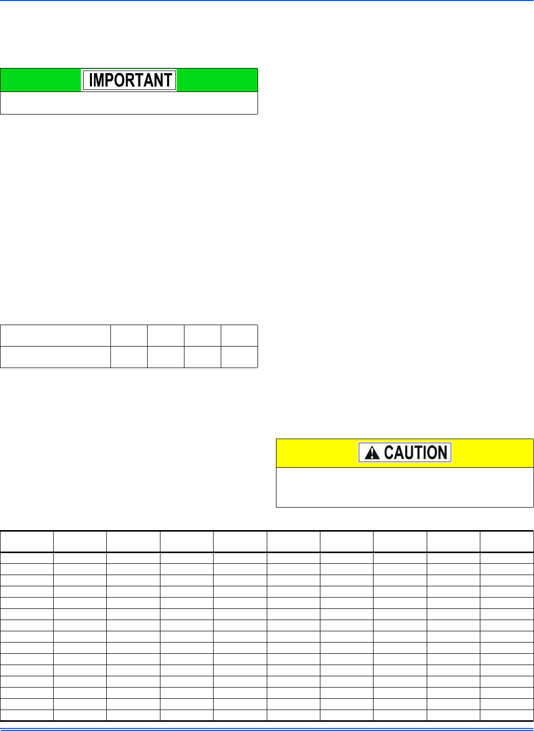
The following steps must be taken at the time of installation to
insure proper system operation.
TABLE 1:
Defrost Initiate Curves
Defrost Curve Selection
Jumper Position
1234
Heat Pump Model
2-Ton
2.5-Ton
4-Ton
5-Ton
3-Ton
3.5-Ton
1.5-Ton
IT IS UNLAWFUL TO KNOWINGLY VENT, RELEASE OR DIS-
CHARGE REFRIGERANT INTO THE OPEN AIR DURING
REPAIR, SERVICE, MAINTENANCE OR THE FINAL DISPOSAL
OF THIS UNIT.
TABLE 2:
R-410A Saturation Properties
TEMP. °F
PRESSURE
PSIG
TEMP. °F
PRESSURE
PSIG
TEMP. °F
PRESSURE
PSIG
TEMP. °F
PRESSURE
PSIG
TEMP. °F
PRESSURE
PSIG
45 129.70 60 169.60 75 217.40 90 274.10 105 340.50
46 132.20 61 172.60 76 220.90 91 278.20 106 345.30
47 134.60 62 175.50 77 224.40 92 282.30 107 350.10
48 137.10 63 178.50 78 228.00 93 286.50 108 355.00
49 139.60 64 181.60 79 231.60 94 290.80 109 360.00
50 142.20 65 184.60 80 235.30 95 295.10 110 365.00
51 144.80 66 187.70 81 239.00 96 299.40 111 370.00
52 147.40 67 190.90 82 242.70 97 303.80 112 375.10
53 150.10 68 194.10 83 246.50 98 308.20 113 380.20
54 152.80 69 197.30 84 250.30 99 312.70 114 385.40
55 155.50 70 200.60 85 254.10 100 317.20 115 390.70
56 158.20 71 203.90 86 258.00 101 321.80 116 396.00
57 161.00 72 207.20 87 262.00 102 326.40 117 401.30
58 163.90 73 210.60 88 266.00 103 331.00 118 406.70
59 166.70 74 214.00 89 270.00 104 335.70 119 412.20
 (8 pages)
 Manymanuals.com
 Manymanuals.de
 Manymanuals.fr
 Manymanuals.it
 Manymanuals.pl
 Manymanuals.cz
 Manymanuals.es
 Manymanuals-pt.com
Comments to this Manuals