York YS Service Manual
Browse online or download Service Manual for Air compressors York YS. York YS Technical data User Manual
- Page / 68
- Table of contents
- BOOKMARKS
- ROTARY SCREW LIQUID CHILLER 1
- Table of Contents 3
- I-ii 035L02381-GB0 4
- 1 SUPPLIER INFORMATION 5
- 1-2 035L02381-GB0 6
- 1-4 035L02381-GB0 8
- Refrigerant Oil Data 9
- Safety Data York “H” Oil 9
- 035L02381-GB0 1-5 9
- 1-6 035L02381-GB0 10
- 2 Product Description 11
- 2-2 035L02381-GB0 12
- 2-4 035L02381-GB0 14
- 2-6 035L02381-GB0 16
- 2-8 035L02381-GB0 18
- 2-10 035L02381-GB0 20
- 3-2 035L02381-GB0 22
- 3-4 035L02381-GB0 24
- 4 INSTALLATION 25
- 4-2 035L02381-GB0 26
- 4-4 035L02381-GB0 28
- 4-6 035L02381-GB0 30
- (field supplied) 31
- 4-8 035L02381-GB0 32
- Solid State 33
- Fused Disconnect 33
- 4-10 035L02381-GB0 34
- 4-12 035L02381-GB0 36
- 5 COMMISSIONING 37
- 5-2 035L02381-GB0 38
- 6 OPERATION 39
- 6-2 035L02381-GB0 40
- 6-4 035L02381-GB0 42
- 7 MAINTENANCE 43
- 7-2 035L02381-GB0 44
- 7.5.1 Oil charging procedure 45
- 7-4 035L02381-GB0 46
- 7.6.4 Refrigerant Charging 47
- 7-6 035L02381-GB0 48
- 7.7.4 Tube Leaks 49
- 7-8 035L02381-GB0 50
- 8 TROUBLE SHOOTING 51
- 8-2 035L02381-GB0 52
- 035L02381-GB0 8-3 53
- 8-4 035L02381-GB0 54
- 035L02381-GB0 8-5 55
- 8-6 035L02381-GB0 56
- 9 TECHNICAL DATA 57
- 9-2 035L02381-GB0 58
- 9.2 Weights 59
- 035L02381-GB0 59
- 9-4 035L02381-GB0 60
- 035L02381-GB0 9-5 61
- 9-6 035L02381-GB0 62
- Information 63
- Required 63
- 10-2 035L02381-GB0 64
- 11-2 035L02381-GB0 66
Summary of Contents
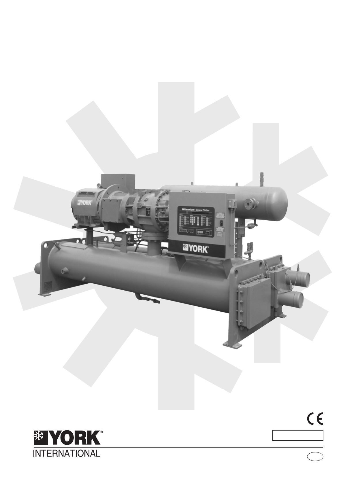
YSSTYLE:REFRIGERANT:DR134aROTARY SCREW LIQUID CHILLERGBINSTALLATION, COMMISSIONING,OPERATION AND MAINTENANCEEffective from 02/00YS PICTURE REQUIRED
Thermal & Acoustic Materials DataHealth Hazard & First Aid Toxicity Index <10 to NES713 Issue 3 (1991): Non-hazardous, non-toxic. No firsta
2 Product Description2.1 General (Figures 2.1 and 2.2)The York YSMillennium™ Rotary Screw Liquid Chilleris primarily used for large air conditioning s
The rotors are manufactured from forged steel and useasymmetric profiles. The compressor incorporates acomplete anti-friction bearing design for reduc
2.3 MotorThe compressor motor is an open drip-proof, squirrelcage induction type. The motor has a D-flange and castiron adaptor mounted rigidly to the
Three sight glasses are provided in the oil separator formonitoring the oil level and verifying performance of thecoalescer element. Liquid oil should
An oil supply line from the manifold at SB-2 is piped tothe capacity control directional valve at Port P. The4-way capacity control solenoid (directio
2-6 035L02381-GB0Figure 2.7 Refrigerant Flow ControlFigure 2.6 Refrigerant Flow Diagram
2.9 EvaporatorThe evaporator is a shell and tube, flooded type, heatexchanger with a distributor trough providing uniformdistribution of refrigerant o
2.13 Water BoxesRemovable water boxes fabricated from heavy gaugesheet steel are fitted to each end of both heatexchangers. The design working pressur
The control centre includes unique safety logic toprotect the unit from damaging malfunctions.Comprehensive information can be displayed in theevent o
High Water Side Pressure Heat ExchangersOne or both of the evaporator and condenser may besupplied with a water side design pressure of 20 bar(subject
3 TRANSPORTATION, RIGGING AND STORAGE3.1 GeneralYS units are shipped as a single factory assembled,piped, wired package, requiring minimum installatio
Form 3 – Motor/Compressor Separate From ShellsShipped as three major assemblies. Unit firstfactory assembled, refrigerant piped, wired andleak tested;
3.4 RiggingThe complete standard unit is shipped without skids.(When optional skids are used it may be necessary toremove the skids so riggers skates
Page Left Intentionally Blank3-4 035L02381-GB0
4 INSTALLATION4.1 LocationYS units are furnished with vibration isolator mounts forbasement or ground level installations. Units may belocated on uppe
4.7 Installing Optional Spring IsolatorsWhen ordered, 4 spring type isolator assemblies will befurnished with the unit (see table below). The 4assembl
4.8 Piping ConnectionsAfter the unit is levelled (and wedged in place foroptional spring isolators) the piping connections may bemade; chilled water,
If pumps discharge through the chiller, the strainer maybe located upstream from pumps to protect both pumpand chiller. (Piping between strainer, pump
4.13 Stop ValvesStop valves may be provided (by others) in the coolerand condenser water piping adjacent to the unit tofacilitate maintenance. Thermom
Table of Contents1 SUPPLIER INFORMATION1.1 Introduction 1.11.2 Warranty 1.11.3 Safety 1.11.4 Responsibility for Safety 1.11.5 About this Manual 1.21.6
Piping should be properly supported toprevent any strain on bursting disk mounting.Be careful not to puncture bursting disk whenthread protector is re
4.19 Electrical ConnectionThe following connection recommendations areintended to ensure safe and satisfactory operation of theunit. Failure to follow
DO NOT make final power supply connections to controlcentre until approved by a YORK representative.To ensure proper motor rotation the starterpower i
MUST be suppressed using a standard R/Csuppressor to avoid electrical noise whichcould cause a malfunction or damage to theunit.To avoid the possibili
4.21.4 Multi Unit Sequence Connections(MUS - TB2: Terminals 1 & 9)For multiple unit installation applications, Multi UnitSequence connections are
4.22.1 Remote Mode Ready to Start Status(RMR/S - TB4: terminals 26 & 27)When closed, these contacts signify the control centre isin "REMOTE&q
4-12 035L02381-GB0-AMBCP-AOIB-ARB-APB-QRCD-QCSDLSTB2TB4TB5TB67 L40TB2 TB5TB4RLCWTSPRCSPCPMSASSIC/S S/S CWP RMR/SR/STT R/LC8NB 5NB15NB1NB1NB15NB14NB1NB
5 COMMISSIONING5.1 PreparationCommissioning of this unit should only becarried out by York authorised personnel.The Operating Instruction manual must
5.2 First Time Start-upDuring the commissioning period there shouldbe sufficient heat load to run the unit understable full load operation to enable t
6 OPERATIONIf the oil heater is de-energised during ashutdown period, it must be energized for 24hours prior to starting the compressor.6.1 GeneralYS
5 COMMISSIONING5.1 Preparation 5.16 OPERATION6.1 Oil Heater Operation 6.16.2 Checking the Oil Level in the Oil Reservoir 6.16.3 Start-up Procedure 6.1
6.4 Normal OperationAfter the compressor reaches its operating speed theslide valve will begin to load, under the control of thecontrol Centre, based
6.8 Operating InspectionsBy following a regular inspection schedule any potentialproblems with the unit can be identified early andattended to before
6-4 035L02381-GB0Figure 6.2 Log SheetFigure 6.1 Start-up, Operation and Shutdown Sequence
7 MAINTENANCEThe Safety Section of this manual shouldbe read carefully before attempting anymaintenance operations on the unit. Thissection should be
7.3 Regular Maintenance OperationsService Schedule MINOR SERVICE( 3 - 6 monthly ) *MAJOR SERVICE ( 6 - 12 monthly ) *All items under Minor Service plu
7.4 Oil Filters and StrainersThe oil return system ensures that oil removed from thedischarge gas by the oil separator and oil reaching theevaporator
3. Open the oil charging valve and pump oil into thesystem until oil level in the oil separator is aboutmidway in the upper sight glass. Then, close t
7.6.4 Refrigerant ChargingWhen opening any part of the refrigerantsystem for repairs, the refrigerant chargemust be removed. If the chiller is equippe
7.7.2 Tube CleaningCoolerIt is difficult to determine by any particular test whetherpossible lack of performance of the water cooler is dueto fouled t
7.7.4 Tube LeaksCooler and condenser tube leaks may result inrefrigerant leaking into the water circuit, or water leakinginto the shell depending on t
1 SUPPLIER INFORMATION1.1 IntroductionYork YS chillers are manufactured to the highest designand construction standards to ensure highperformance, rel
7.9 Testing Motor Winding InsulationWith the main disconnect switch and compressor motorstarter open, test the motor as follows:1. Test the insulation
8 TROUBLE SHOOTING8.1 General RequirementsUnits are not generally user serviceable and no attemptshould be made to rectify any faults found with the u
Displayed Reason forShutdownControl Function Possible Cause Recommended ActionAC UNDERVOLTAGEMotor current below 10%for more than 25 secondsduring RUN
Displayed Reason forShutdownControl Function Possible Cause Recommended ActionLOW EVAP PRESSUREEvaporator pressure below172 kPaBlocked / dirty evapora
Oil System Faults Detected During Regular InspectionsFault Possible Cause Recommended ActionOIL RESERVOIR LEVEL DROPPINGWHILE UNIT SITTING IDLESystem
Electrical System Control Centre Initiated Shutdowns - Manual Reset RestartDisplayed Reason forShutdownControl Function Possible Cause Recommended Act
Other System Faults Detected During Regular InspectionsFault Possible Cause RemedyEXCESSIVE NOISE I VIBRATION Liquid refrigerant entering compressor C
9 TECHNICAL DATA9.1 DimensionsNotes1. Unit height includes steel mounting plates under tube sheets. To determine overall installed height, add 22 mm f
Notes1. Unit height includes steel mounting plates under tube sheets. To determine overall installed height, add 22 mm forneoprene isolators (25 mm fo
9.2 Weights035L02381-GB09-3Shell CodeCooler-CondenserCompressorShippingWeight(kg)OperatingWeight(kg)RefrigerantCharge(kg)Shell CodeCooler-CondenserCom
1.5 About this ManualThe following symbols are used in this document to alertthe reader to areas of potential hazard.A Warning is given in this docume
9.3 Motor Weights9.4 Optional Solid State Starter Weights9-4 035L02381-GB0Motor CodeWeight50 Hz (kg)5 CC 4905 CD 5085 CE 5085 CF 6625 CG 6895 CH 8755
9.5 Process and Instrumentation Diagram035L02381-GB0 9-5
9.6 Water Box Nozzle ArrangementsNotesA. Standard water nozzles are furnished as welding stub-outs with Victaulic grooves,allowing the option of weldi
10 SPARE PARTSIt is recommended that the following common spareparts are held for preventative of correctivemaintenance operations.Other spare parts v
Page left intentionally blank10-2 035L02381-GB0
11 DE-COMMISSIONING, DISMANTLING AND DISPOSALNever release refrigerant to theatmosphere when emptying therefrigerating circuits. Suitable retrievalequ
Page left intentionally blank11-2 035L02381-GB0
YORKEuropeSubject to change without noticeALL RIGHTS RESERVEDPart No. 035L02381-CB0 (02/00)YORK INTERNATIONAL LTD.Gardiners Lane South, Basildon, Esse
Refrigerants and OilsRefrigerants and oils used in the unit are generallynon-toxic, non-flammable and non-corrosive, and poseno special safety hazards
1.9 Material Safety DataRefrigerant Data:Safety Data R134aToxicity Low.In contact with skin Liquid splashes or spray may cause freeze burns. Unlikely
Spill/leak procedure Ensure suitable personal protective clothing and respiratory protection is worn.Provided it is safe to do so, isolate the source
More documents for Air compressors York YS

Related products and manuals for Air compressors York YS
 (100 pages)
(168 pages)
(60 pages)
(76 pages)
(100 pages)
(168 pages)
(60 pages)
(76 pages)
© 2020, manymanuals.com. All rights reserved. | 1.481 s |
 Manymanuals.com
 Manymanuals.de
 Manymanuals.fr
 Manymanuals.it
 Manymanuals.pl
 Manymanuals.cz
 Manymanuals.es
 Manymanuals-pt.com
Comments to this Manuals